
Main drivers.
The main drivers are obviously a large part of what the locomotive looks like, and I was keen to do a good job on replicating them. This was the second pattern I had made, the first being the front truck. By now I had decided I was on a one way trip and it was too late to jump so I had better forge ahead.
There were a number of decisions to made in creating the patterns for the drivers. Mostly this came down to how much money you wanted to spend and how much detail you got for your £. You also needed to decide how much detail you could sacrifice to get the cost to a reasonable number.
Just a few word for the uninitiated and those not that familiar with steam locomotives that may light upon this page. Steam locomotives work basically by converting the energy contained in the steam via reciprocating pistons in the steam cylinders into a rotary motion. To do this the wheels are connected by rods that transfer the reciprocating action of the pistons into the rotary motion of the wheels All this linkage is heavy and where it connects to the wheels on the crank pins it creates widely out of balance forces. To combat this each wheel has a balance weight opposite the crank pin. So much for theory then, what's so complicated about that ? All you need are eight wheels with some weights on them. Well yes and no, because dependant on where the wheel is means that there may be more or less force acting on it due to the reciprocating mass attached to it.
With it so far? Well there is one final double six to add to the mix. The wheels are handed as one side leads and one side trails. What do I mean by that well it means that the balance weights on the wheels are in different positions for one thing. Basically on one side of the locomotive all the crank pins will be 90deg ahead of the opposite side and that's as far as I am going on theory as my head is hurting. If you need more explanation do a search on how a steam locomotive works and see what you get.
So lets get back to the patterns as I said a number of decisions had to be made prior to making the patterns. This boiled down to a few key points. Did I want the wheels to have flat backs with only detail on the front. Did I want to add the balance weights on after casting as this would cut down on the number of patterns but be less realistic, and how much money did I want to spend ?
Well I wanted full detail on the wheels,I did not want to add the weights on after casting and I wanted to spend as little as possible, so over to you Terry.
Well after some deep breaths Terry came up with the following solution that seemed to tick all my unreasonable boxes. The locomotive although it has eight wheels only has three different wheel types. They are the main, leading and trailing and intermediate. So first off was a master pattern from this 6 castings in aluminum would be cast to produce the base form for the three different wheels and left and right hand versions.
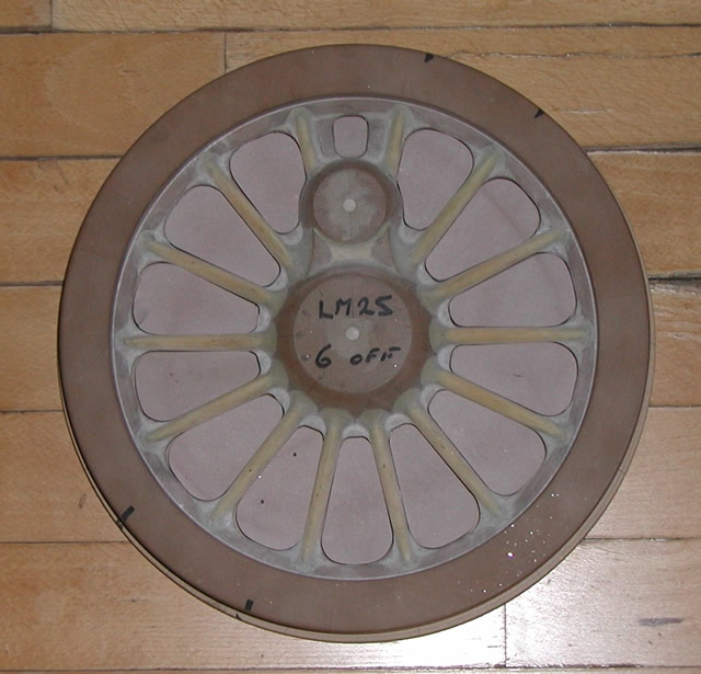
Master pattern ready to pour in aluminum
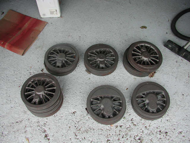
The best pattern to see the differences from our staring point is the main driver. The next two shots show the patterns for the left and right hand version
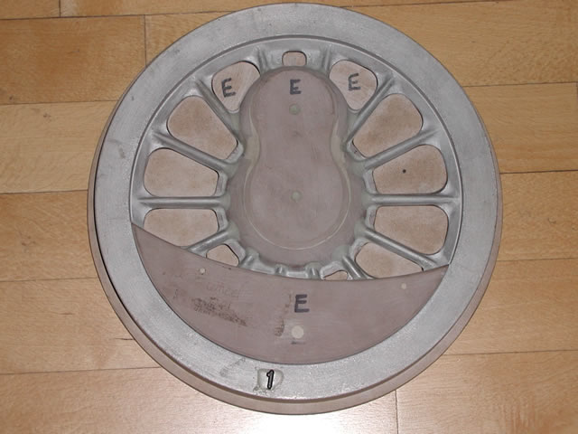
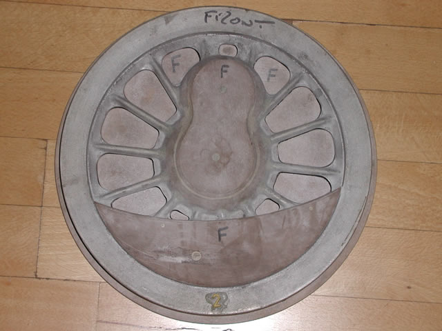
And by way of comparison the three patterns shown together
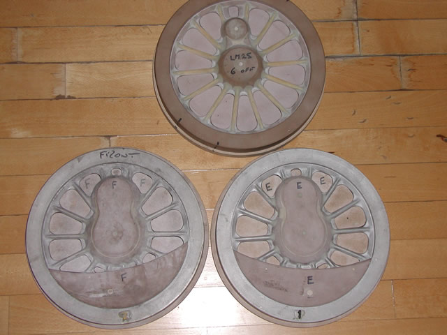
So we now had all the patterns and it was off to the foundry to get the first pour done
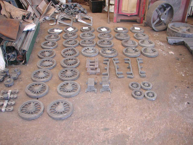
First pour of 32 wheels and front truck components.
Second pour, main's bottom right, intermediate; center upper, and the rest are leading and trailing
The machining operations of the wheel sets has been going on over a number of years. This has been due to a number of factors mostly associated with spreading the cost of pattern making casting and some major mistakes on my part. Looking through the photographs of the machining operations its like a bit of all our yesterdays as it encompasses at least three workshop layout changes, the workshop extension and the sale of the Bantam 2000 this year followed by the purchase of the Dean Smith and Grace lathe this year.
So don't be surprised if the background changes on these photographs it surprised me as well ! Also as I felt I was falling behind on this part of the locomotives I sub contracted some of the work to John Dunn Engineering and you will see that his work is marked on the photographs.
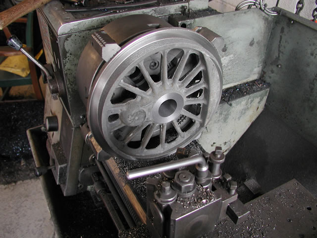
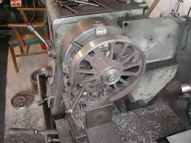
First job was to grip the casting in a four jaw chuck and face of the center boss machining the axle hole to size and part rough turning the rim. The bore would be used later for final machining so had to be on size.
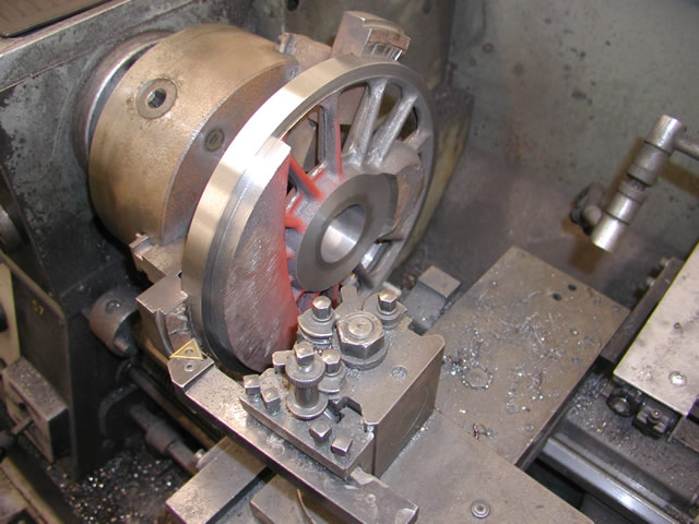
The wheels were then turned around and gripped on the roughed rim in the soft jaws of a three jaw chuck. The rim was again roughed to the previous diameter and the center boss was faced to the correct width.
Once the faces and bores had all been machined to size a mandrel was made to a good fit on the bore and all the wheels were turned to finished outer dimensions. The rims were all skimmed to the same size ready for the steel tyres to be machined.
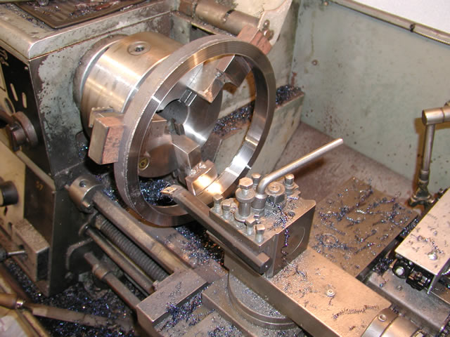
The same soft jawed chuck was used again to finished the tyres to size and true up the width
At this point the wheels lay around the workshop for probably 18 to 24 months as other things took precedent so fast forward to early this year. I contacted John Dunn and discussed what I needed doing John and I agreed a price and work on the wheels started up again. Johns first job was to bore out the crank pin bosses and face them to size
 .
.
Once this was done the next job was broaching the key ways in the wheels and the main crank pin. This is fairly complicated because of the main driver crank pin having a square on it to accommodate the return crank. So the relationship between the two key ways is a bit of a mind fizzler.
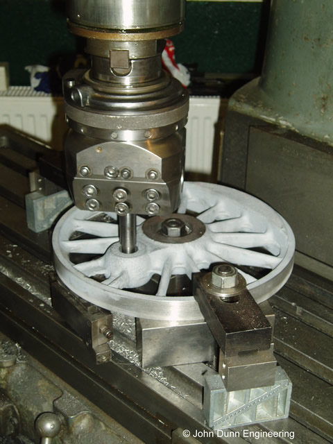
John's big idea the fixture used to make sure the key ways were in the right relationship
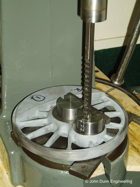
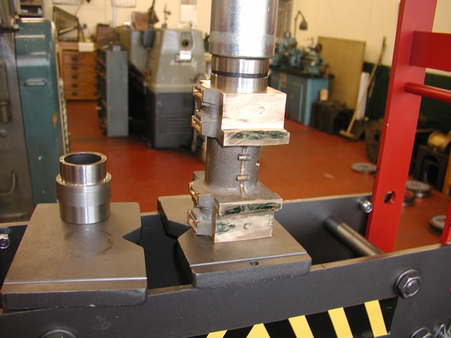
Using the bench press to broach out the key ways
John and I spent a fair bit of time arguing about the relative positions of the axle key way and the crank pin key way. Being the designer and having drawn up all the parts I was fairly sure I was right. but after long a torturous discussions we finally agreed ...I was wrong !
The big argument note the relative positions of the key ways in relationship with the axle key way and yes there is also the left and right side to factor in as well. Its not just a matter of mirroring the drawing as i found out , I eventually convinced myself that the drawing was right but in fact i had forgot to take into account that i was looking from one side only. John on the other hand twigged this fact but I still to an age to be convinced of my error.
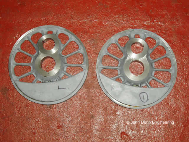
The two sets of drivers crank pin bores and faces machined and the key ways cut, now ready for tyre fitting.
After the work on the drivers John started on the crank pins. These once machine will be through hardened and ground.
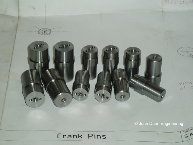
Crank pins ready for hardening
Whilst John was getting on with the drivers I was correcting a mistake I had made on the axles. This proved once again that things can only get worse and sometimes its better to start again which is what I did. This also gave me the opportunity to give my "new" DSG lathe a work out. I had to machine the 6 new axles all in EN24 as quickly as possible as I wanted to make a trip to the heat treatment shop with the springs and only wanted to go the once.
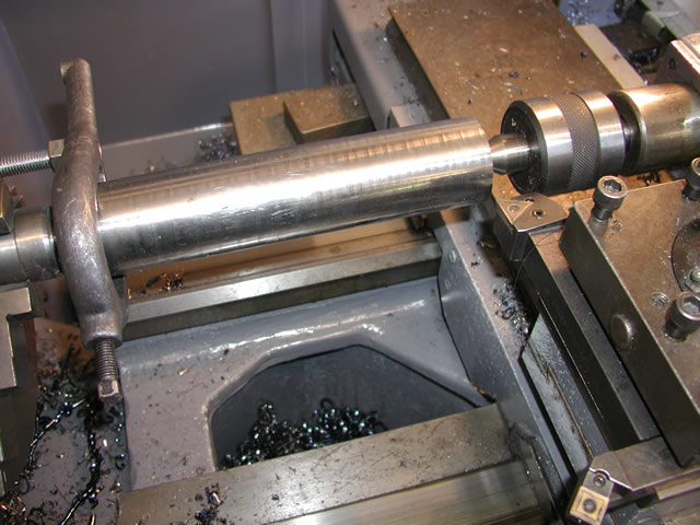
Blank set up between centers ready to cut
First roughing cut at 0.1" deep
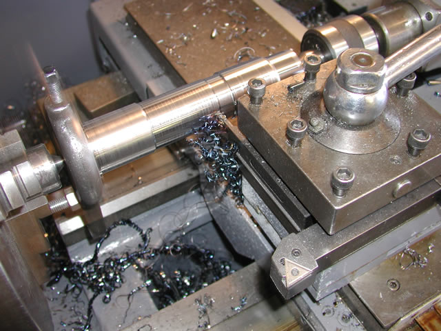
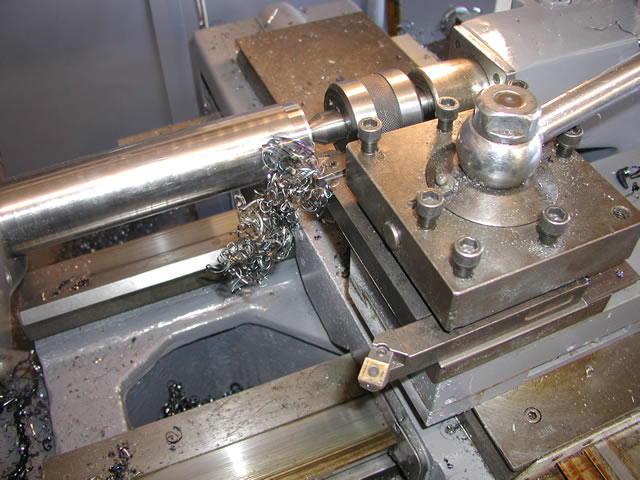
Relieving the centre portion using the radius tool
First side complete
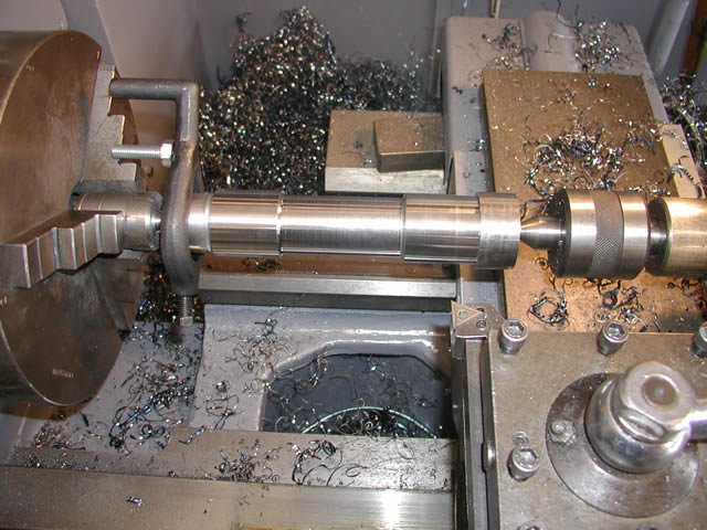
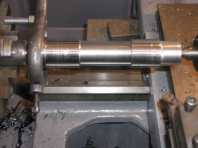
Completing the second side
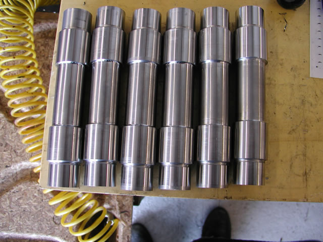
All six shafts turning completed.
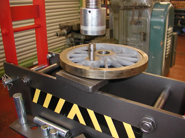
After dropping the shafts off at John's I brought away the drivers so I could fit the tyres to the wheels prior to the wheels being pressed onto the axles for machining.
Using the six crop ends from the axle blanks I made two sets of three posts. Three to hold the wheel and three just lower than the rim so the tyre cooled just proud of each face of the rim
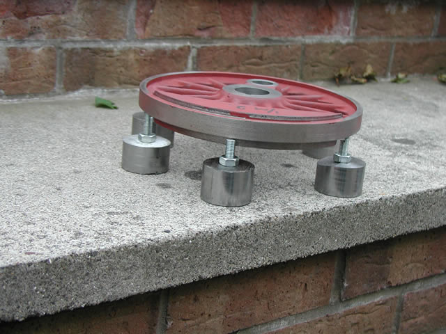
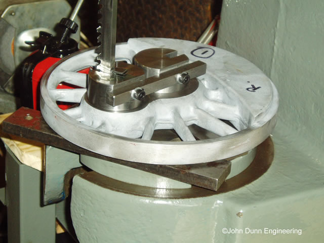
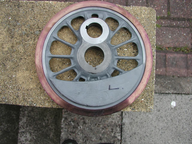
Wheel sitting on the support posts with the tyre posts in place
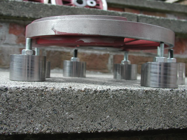
Underside of wheel showing placement of the posts
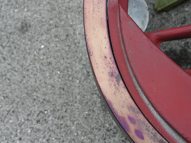
Just how much expansion you can get on a 10" mild steel ring in the kitchen oven. I think you can see its about 1/32" and that was at gas mark 9 after this one I turned the oven down to six because it took too long for the tyre to cool. You can see the gap at the top of the picture with the support post below clearly visible.
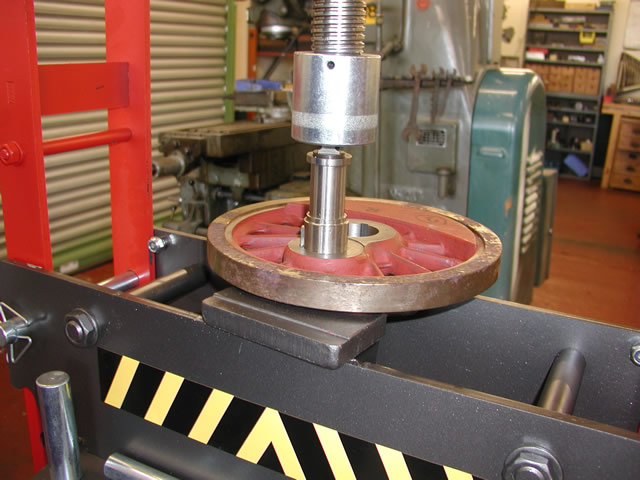
The completed wheel with tyre shrunk on
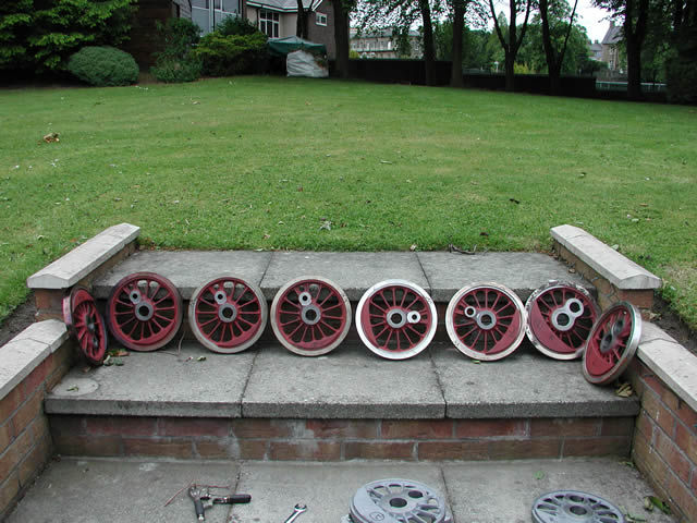
A full set of drivers with tyres fitted, the steps up to the garden made a handy workbench as they are not too far from the oven. When I think of it perhaps I should have cranked up the barbi and heated the tyres in that. Then thrown a steak on to celebrate.
The axles are now away getting hardened and I am looking for a cylindrical grinders to finnish them to size. Once that is done the big assembly day comes hopefully before the end of July so keep checking back I will post an update as soon as the wheel sets are assembled. Till then I have plenty more to get on with.
Well 6 months later and i have finally got all the drivers together. The outsourcing of hardening grinding and some self inflicted spark erosion has added months to where I expected to be so the following are a few snaps of the assembly of the main driver wheel sets.
All work was done at John dunn's workshop as he had invested in a nice 30T press and also had been heavily involved in the machining of various parts of the wheel sets and we both wanted to see what the finished article looked like.
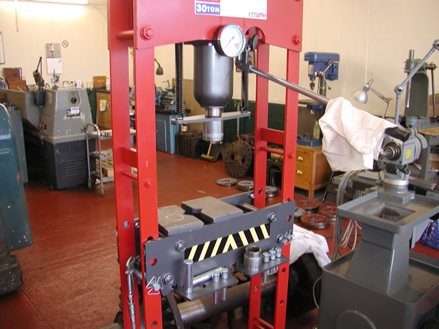
John's weapon of choice the new 30T press.
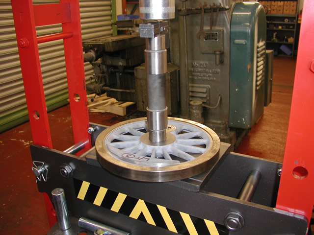
First job was pressing the bearings in followed by the seals the dolly on the left is for pressing the bearings home.
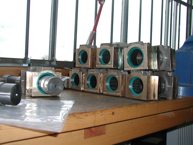
All box's ready for the shafts
Next job was to press the crank pins in, these are the leading and trailing pins
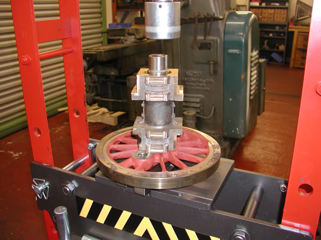
Next were the main driver crank pins, to ensure correct alignment as they have a square seat for the return crank, the crank pins are located with a key.
All crank pins fitted to wheels
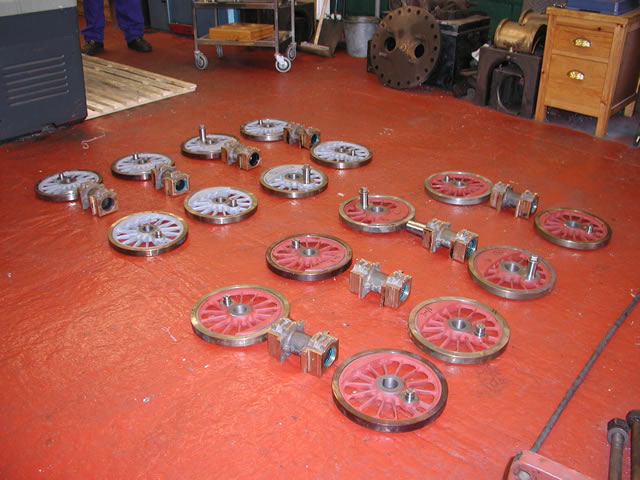
Both John and I, were obsessed with getting the wheels in the correct locations and the correct hand. We also had to make sure that the right hand side led. So to do this everything was laid out on the floor in its correct position and we then had an agreed pattern of which wheel we picked up from which set first, then pressed on to ensure we did not drop a clanger. The wheels remember are three different patterns but could fit to any of three axles on any side of the axle. only the main driver axles were a different diameter. All very anally retentive I agree but it did work.
So next was pressing the shafts in.
Each shaft was keyed at 90 degrees to ensure correct alignment. we then spent a lot of time making sure this first pressing into the wheel was perfectly vertical in all planes
Next the box was dropped on ready to press on the other wheel
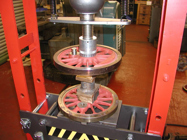
With the key way ensuring the wheels were correctly quartered the wheel was pressed on
For those not entirely sure about the term quartering I would suggest a net search for an explanation as its too much typing for me. It has also been covered in greater detail many times better than I could do it.
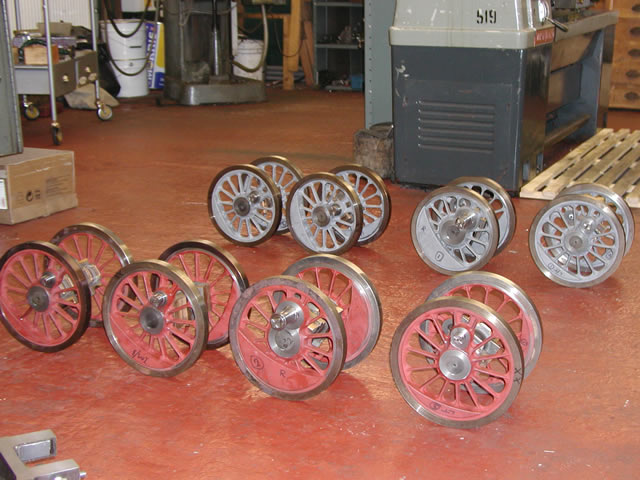
9 hours later all the wheel sets are assembled
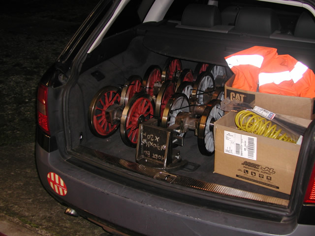
6PM and the sets together with the axle box machining jig are ready or the 170 mile trip home.
The assembly of the wheel sets were very much a collaborative effort between John and I. John as been extremely helpful in getting the wheels to this stage and although things started off as a business transaction we have become good friends over the last few months. Indeed I always look forward to his phone calls generally starting off "no there's not a problem but"
John being the owner of a steam locomotive himself can bring real life experience to the work in hand which has been invaluable to me. For anyone wanting quality work done I can not recommend him highly enough.
So the end of another chapter next will be the wheel profiling but once again that's for the future.