
Coupling Rods
In the help section of the site I ask for any people who can assist with CNC machining. Surprisingly I find that every now and then someone contacts me with just that most rare of commodities help. In this case Paul Foster of Appleby engineering dropped me an email about his business set up in a picturesque part of Yorkshire not that far from here as it turned out.
Paul had just invested in a new Haas tool room mill and was looking for something to wear out a few tools on. I was looking for someone to do my rods and motion parts so not quite a marriage made in heaven but close. I asked Paul to take me a few snaps of the operation and he kindly obliged. Not doing the job means not much on the description front but interesting non the less for those who have not been involved in CNC work before.
Most of the machining shots are of the main rod although the principals are the same for the rest .
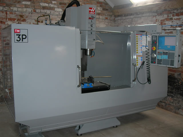
Hass Mill, Paul's weapon of choice.
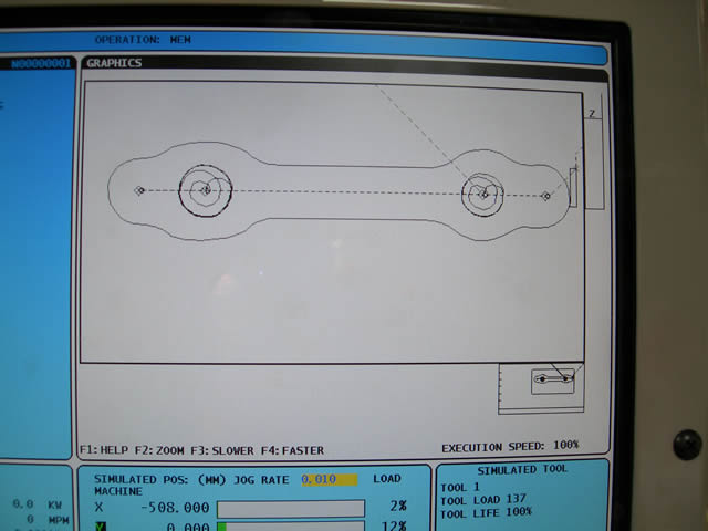
Program screen Paul enters the information direct from my 2D drawings not that I understand, but it works?
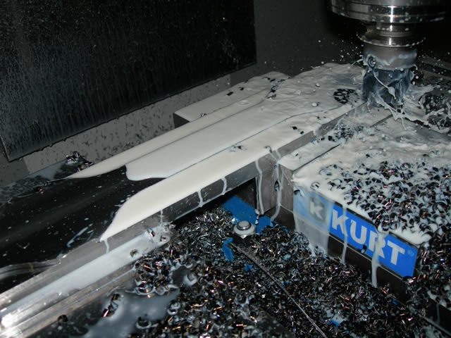
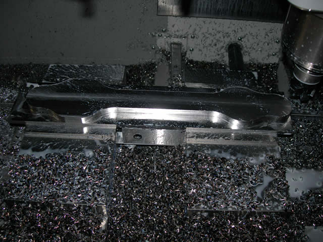
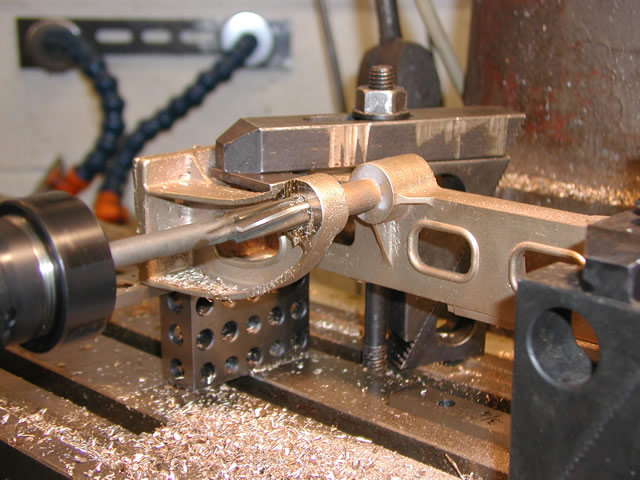
Roughing out the main rod.
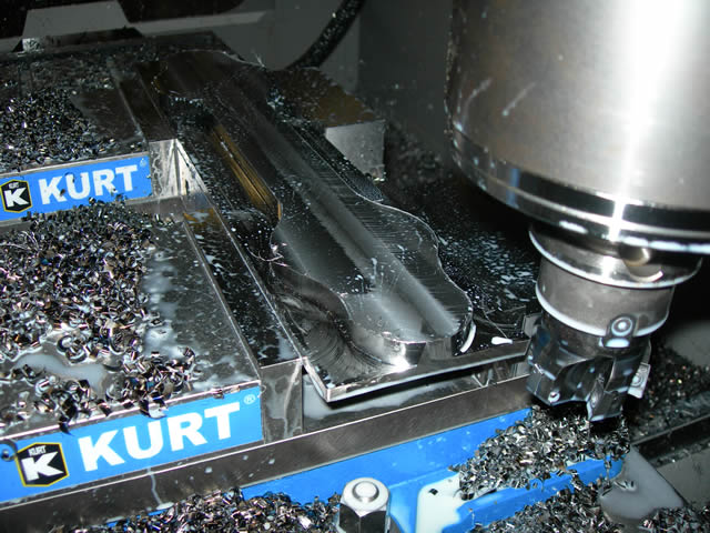
starting to take shape.
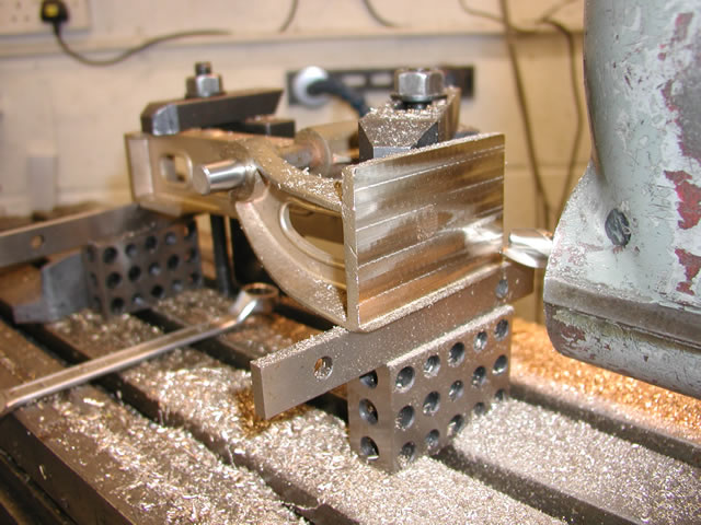
First side done.
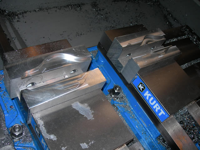
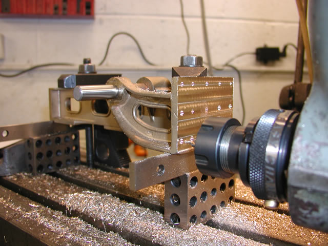
Soft jaws curt to shape to hold the rods for boring and fluting.
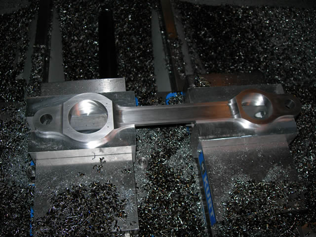
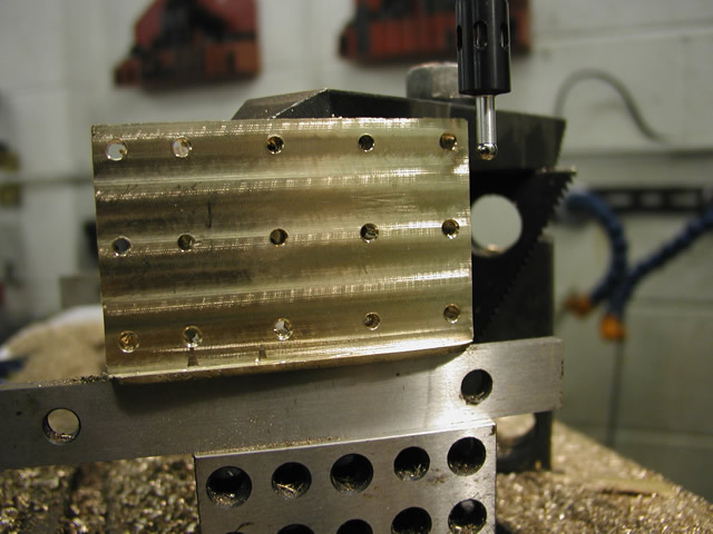
Bearing holes done.
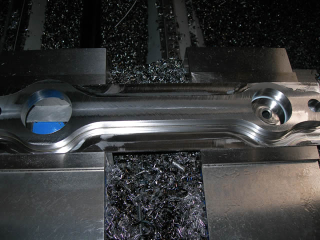
Fluting on the side complete.
Fluting of all rods done ready to start on the edges.
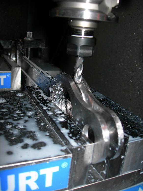
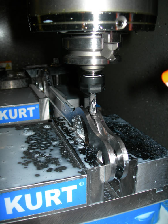
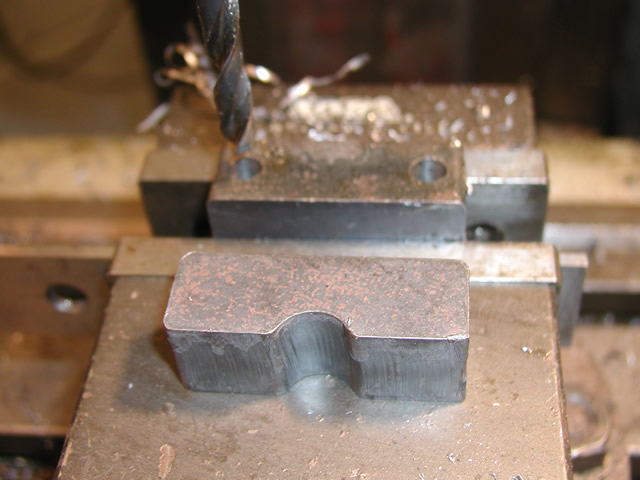
Two shots of the fluting of the main rod, the cutter here is following a circular ark quite tricky.
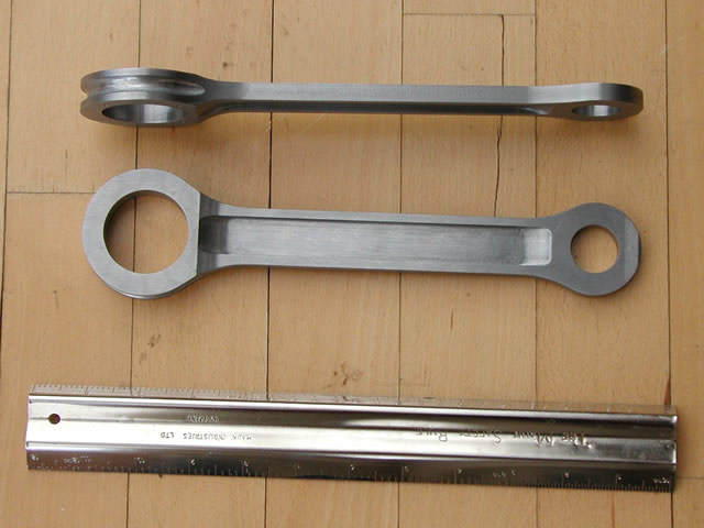
So basically that's the main machining done the rods turned out fine all I need to do is fit the bearings.
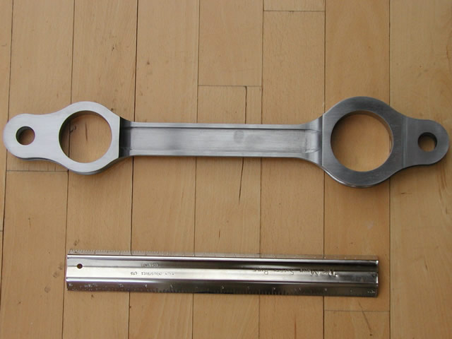
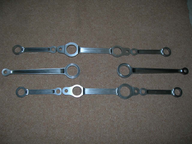
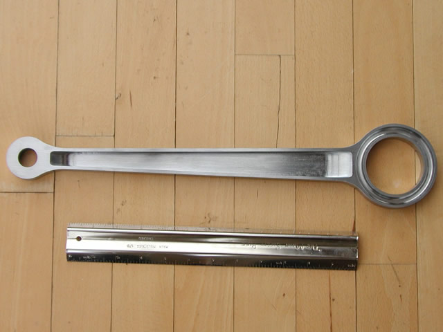
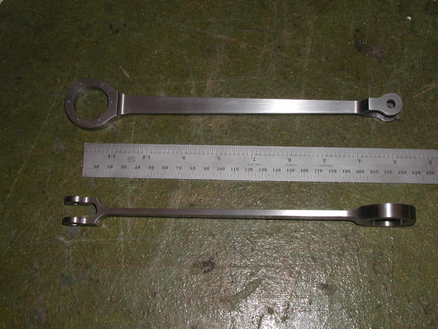
Two shots of the main rod showing the fluting.
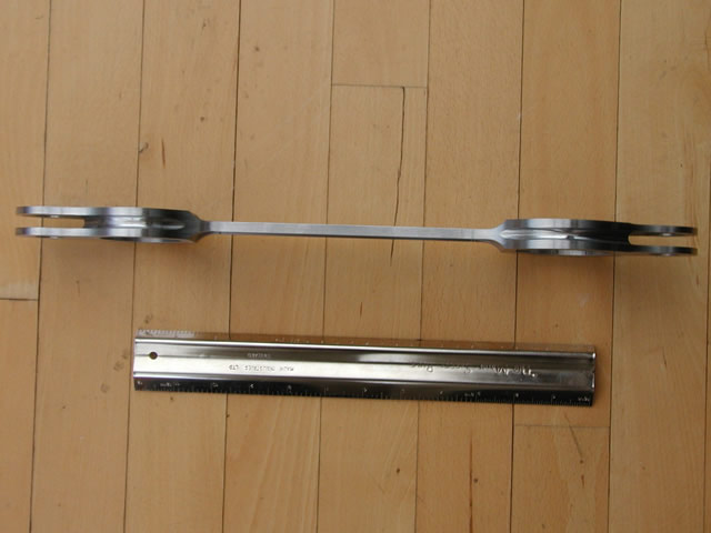
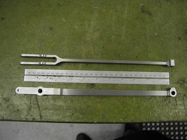
Piston Rod.
Leading and trailing rods.
Paul is currently taking a break to get his BR class 40 ready for the 2010 Harrogate show. He tells me he will be on the 7&1/4 stand so if you need some work done why not ask him there. He is getting a web site together which I will add when its up and running. As soon as the rest of the motion is done I will add pictures of that as well
May 2011
As promised here are the balance of the motion components recently delivered by Paul.
Valve rod
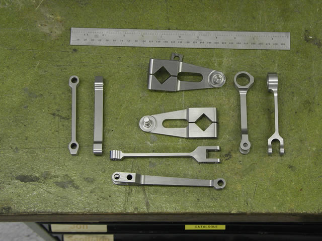
Cranks, lifting link, leading rod combination rod.
Eccentric rod
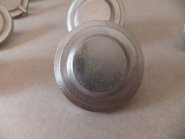
The bearing caps on the 25NC are/were aluminum so i thought i would replicate the parts in that material. Having looked at the ones on 3405 in the UK i wanted to get the rough cast finnish that is so evident on them. So I decided rather than machine from the solid which would have been relatively easy i would RP them in wax and get them lost wax cast, i am very happy with the results which have turned out with just the right amount of patina on them and will polish up nicely
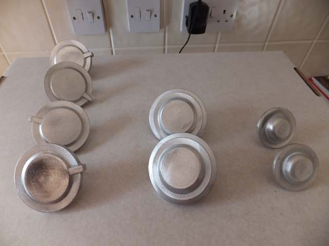
All the caps as cast
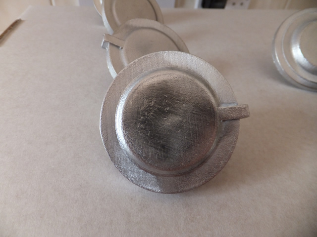
With a little bit of a rub
More fettling
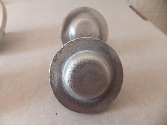
Ready to machine
Next job on the motion to tackle was the motion girders, these items were rapid prototyped a good few years ago . They were done semiprofessionally with a department of a local university that did paying work. However they were provably at the begriming of their knowledge and also machine sophistication. So they had a number of challenges and were also at the outer limit of the foundry who were more used to doing Doug Hewson trinkets than a 10" X 3" X 2" lump. So there were a few blow holes to fill but as I only made one off of each what I had was what I had..
After setting up the casting square first job was too drill and ream the holes were the reversing link shafts fit, My plan then was to use this shaft location with a piece of silver steel through it as the datum to machine everything else off,
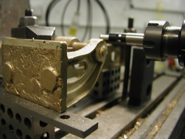
Using the electronic edge finder to center the boss
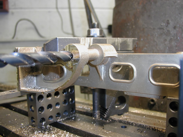
After facing and center drilling the boss a hole was drilled to suite the reamer
Reaming the hole with the right angle head attachment on the Bridgeport
Facing off the mounting face with the RA head
Center drilling and drilling the mounting holes. 70% of them were left slightly undersize so I can ream through from the mounting bracket and use home made fit bolts as per prototype, easiest thing to use would be shoulder bolts but you cannot get them in small sizes with a hex head only allen heads and I don't want a dead rivet counter on my conscience.
Finding the edge so I can index over and machine the faces of the shaft bosses. DRO's make all this sort of coordinate machining a doddle compared to the days of worrying about backlash
Machining the inside faces
Last job was to face off the other end. I did not drill any of the mounting holes on this end as they are easy to drill through from the bracket and I will also ream through for fit bolts.
Before machining the other side of the motion brackets I wanted to machine up the reversing shaft bearing blocks so I can fit them while the girder is still on the machine and ensure as good an accuracy as is possible,
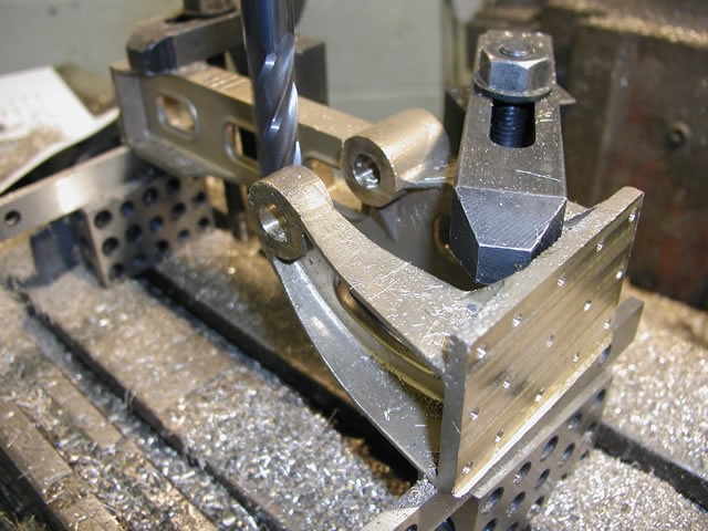
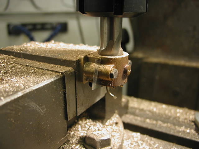
Drilling and spot facing the bearing casting
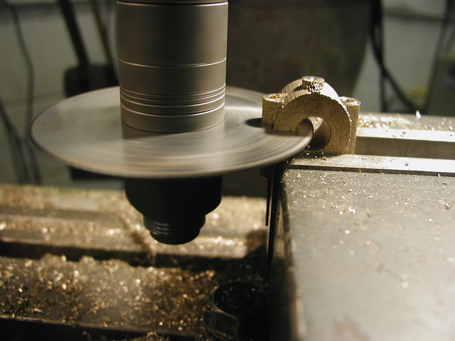
Slitting the cap off
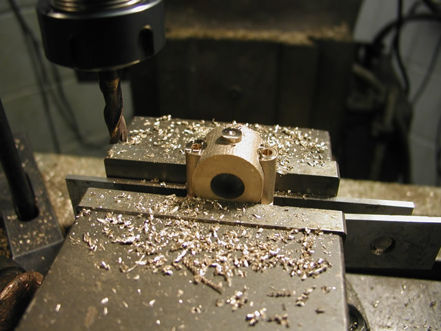
Bearing in two halves
Drilling and reaming the hole two pieces of 10 thou shim in place to give it some grip allowance
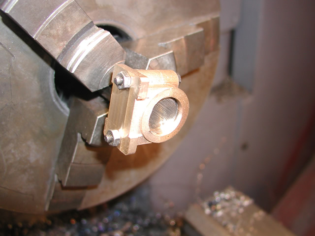
Mounted on a mandrel in the lathe ready to face the boss and recess it for the bearing
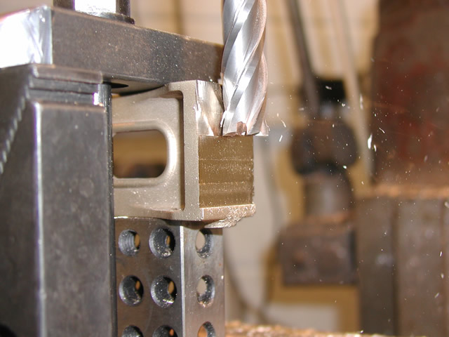
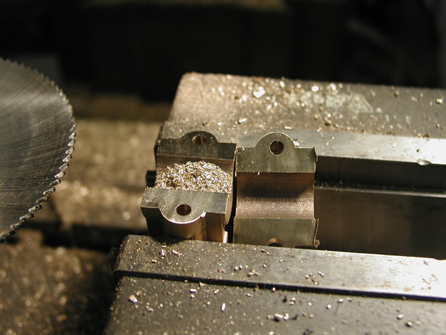
Next jobs were the split bearings that fit into the bearing blocks and the reversing shaft. Both turned out to be marathons not sprints. The bearing blocks need splitting so first job was to slice up the raw stock so it was back to the slitting saw.
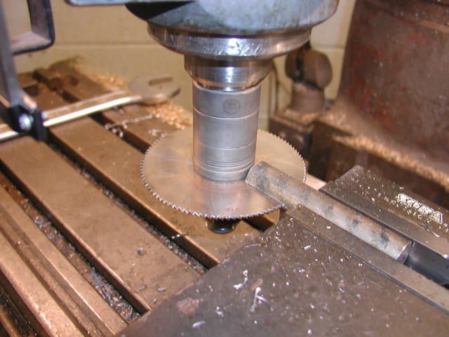
Once I had the material in two it was then time to rake out the oxy-acet gear and braze them back together again. The into the four jaw to machine to size.
Turning up caps
Once done the caps were parted off.
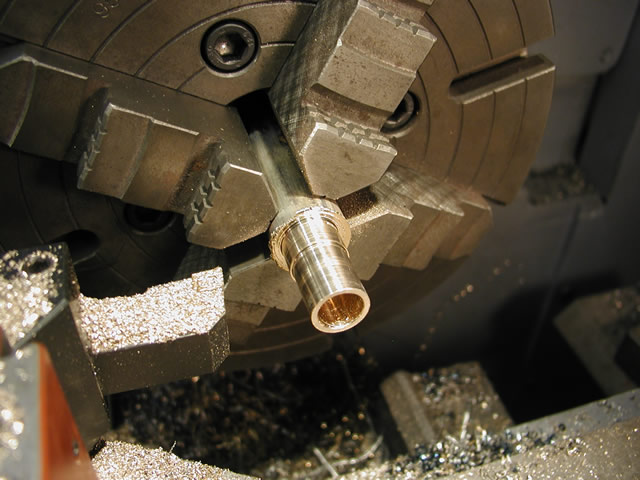
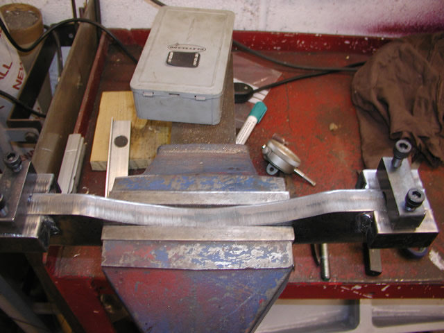
Next job was the reversing shaft which has a big bow in it so also requires a jig for bending. Shaft was a simple turning job
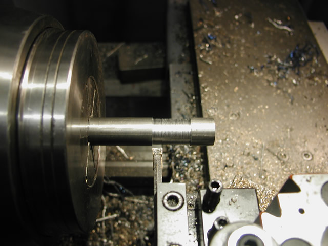
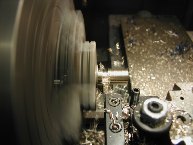
Turning the bearing locations
Last job should have been to cut to 1/8 wide key ways but I am short a cutter so that will have to wait. So I moved onto making the bending jig.
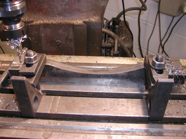
The jig started off as a laser cut form that I then drilled holes in that corresponded to the bearing keep locations
Drilling the bearing keeps
Jig ready for the shaft and some heat.
To be continued