Cradle
The cradle casting was one of the most complicated drawings I tackled but not half as complicated as the pattern eventually turned out. Terry in his usual style was able to produce a spectacular piece of work. This one even including sliding blocks that were retractable, so the pattern could be removed from the sand after" ramming up"
As usual my drawing was a direct copy of the original modified to suit my construction method. In this case the cradle had a substantial tongue at the front that fitted into a corresponding slot in the frames. In the original drawings the frame was covered by four separate drawings and No., 197 detailed the area of the cradle and also covered just about where I was going to split the frame and form the cradle casting.
Click here to have a look at the detailed drawing.
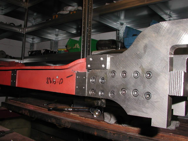
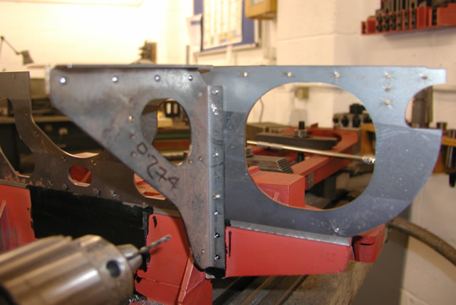
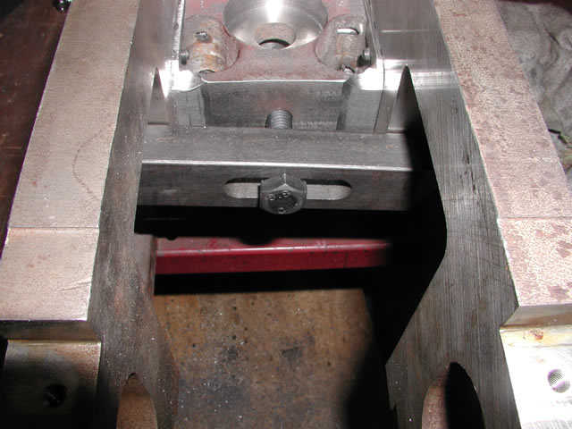
Fit cradle here, you can see the pocket machined in the side frame
The cradle turned out to be over 2Ft 7" long and I was worried about how this would be supported as it was a substantial lump of cast iron. I have see similar castings produced in the states for 1"1/2 scale locomotives where the cradle was made from aluminum or is that all-loom- in- um? Well as I did not know any AL founders I stuck with the CI route. To try and de stress the bolts the cradle sits in the above pocket and also along the top edge, just behind where the curve on the top side ends above the last four bolt holes in the above picture. In a nod to overkill I hope , it is also secured by 24 M6 cap screws.
So before a start could be made it was off to the founders with Terry's pattern, a few months later I got the call from Geoff that the casting was ready to pick up. "and by its been a bugger you know all them cores and lal bits to glue up"
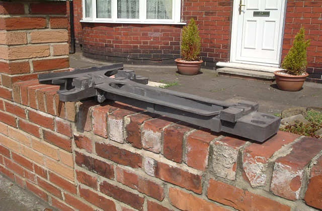
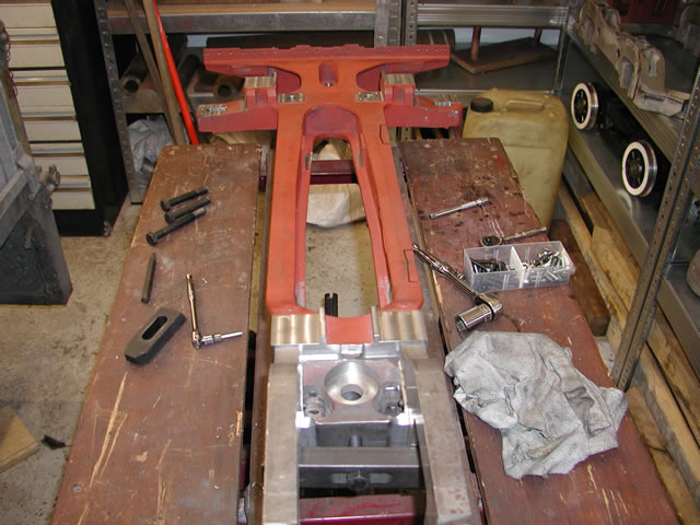
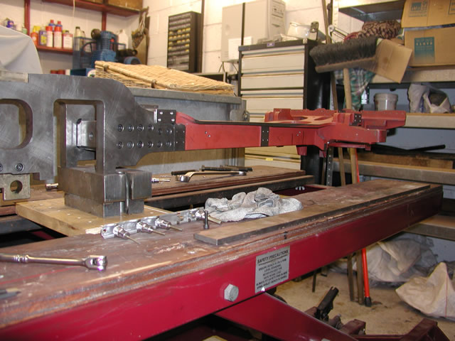
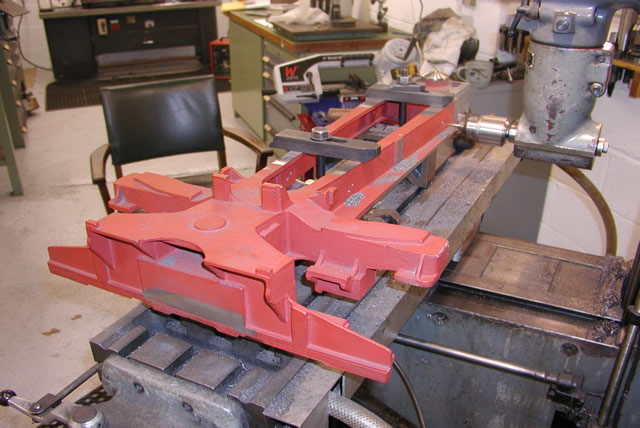
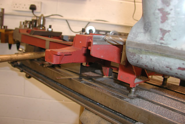
Two views of the cradle taken when I stopped off in Redcar after picking it up. 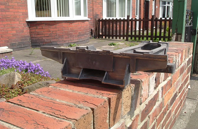
After some more fettling and a good scrub with a rotary wire brush and a coat of red primer the casting was ready to machine. As I think I mentioned in another area I like to do as much machining as possible at one setting to reduce the chances of errors creeping in. However this was not going to be so easy as the casting was too long and too wide to get everything done in one setting on the Bridgeport table.
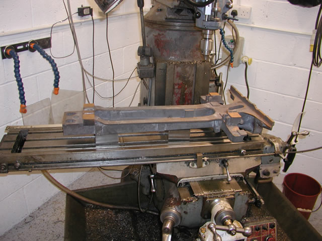
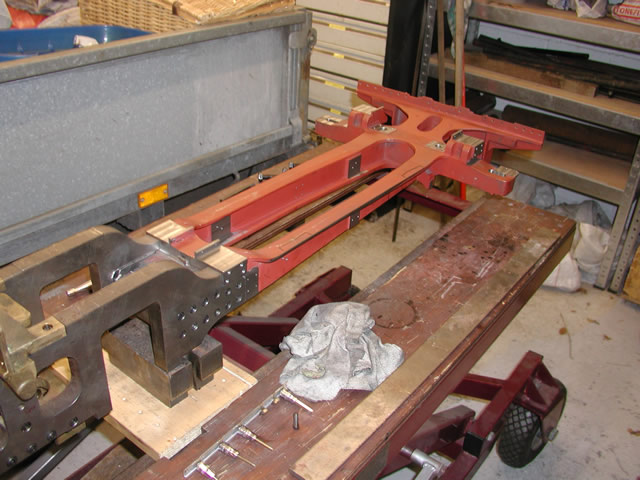
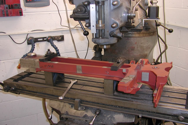
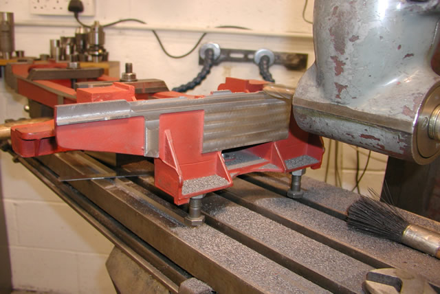
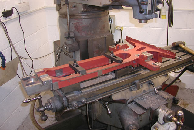
Sitting on the mill for a test set up prior to fettling
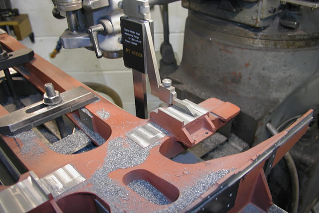
So this one was going to be a challenge I would need to machine both the top and the underside. Front top, rear top, rear end . This all worked out at 4 different positions on the mill table which is about 4 more than I like. So where to start ? well first thing I needed to do was square the casting up to so it would be centered in all axis. This would seem to be straight forward as there were some substantial relatively straight edges on it. But because of its length and shape there was slight twisting and curvature to contend with and what you ended up with was the best compromise.
Using an electronic edge finder to set the casting datum's.
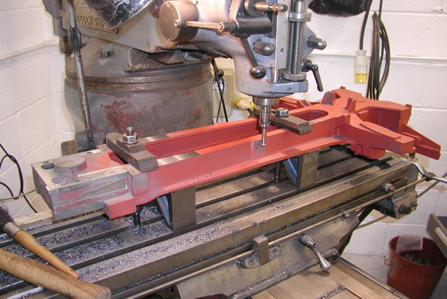
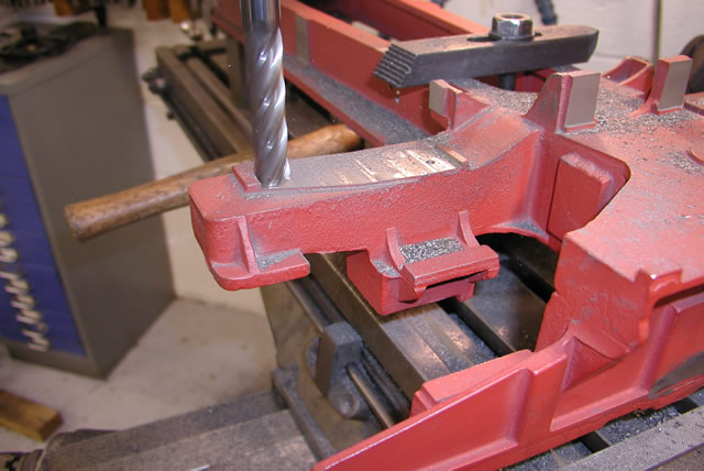
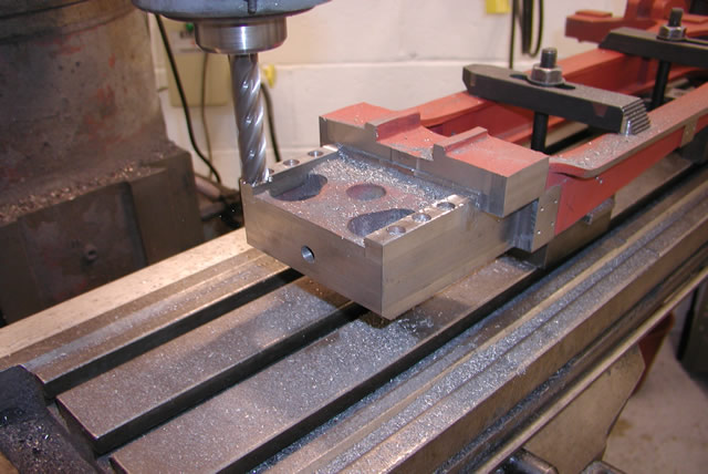
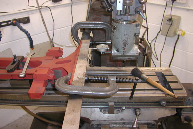
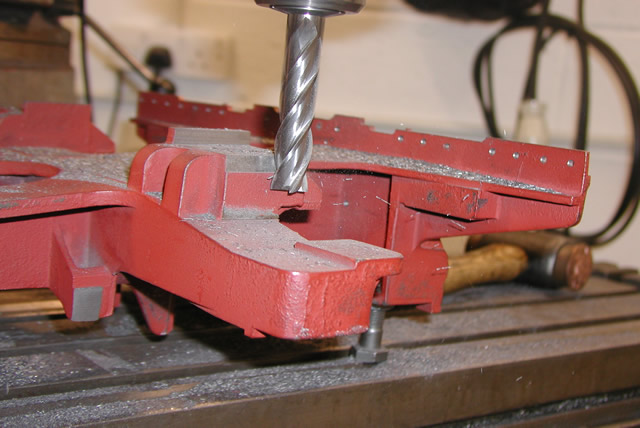
So you have to start somewhere and the most important bit to get right was the tongue at the front which had a number of edges to keep square. This could best be done by machining the underside first and so the casting was set up on two blocks to clear some of the protrusion on the top. After spending quite some time getting the thing relatively square I took a skim off the front only to find that front to back was about 25 thou out of level. To combat this I slackened everything off again and put some shims under the rear block. Then just to keep things tidy I also took a couple of cuts of the underneath of the web where the blocks would sit when the casting was turned over.
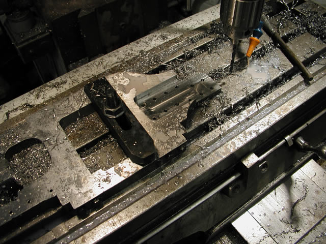
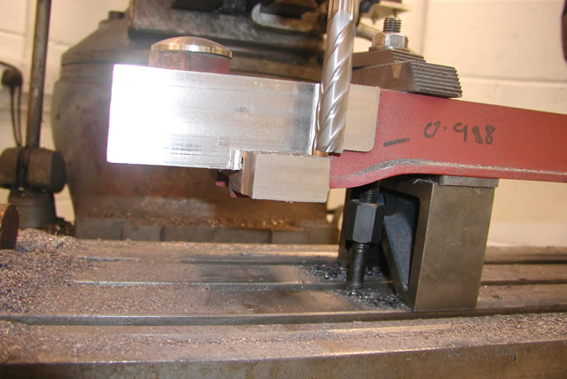
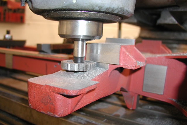
First cut on the tongue, the block with 1.733 on it is the R/H front boiler support
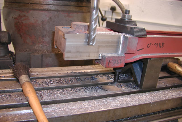
With the casting set up as in the above picture I could machine four sides of the tongue I could also machine the bottom face of the boiler support which sits on frame top as well as the front face of the block behind the support which also buts up to the frame. The last thing left then was to take a skim off the front face
Front face being machined
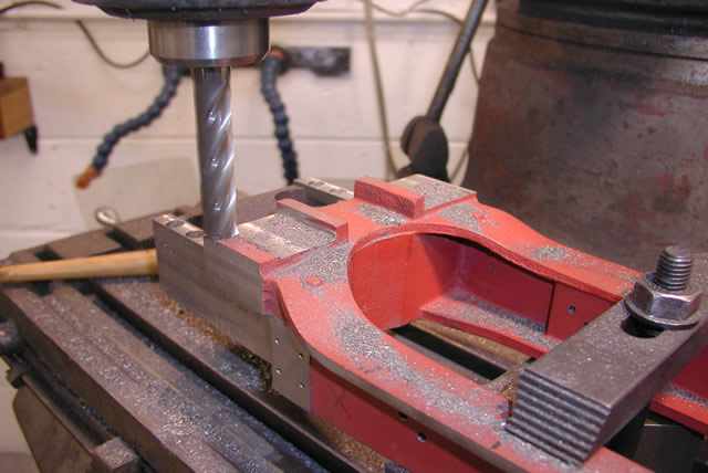
Once the tongue had been cleaned up and machined to size the next job was to machine the fulcrum boss for the rear truck pivot.
A couple of shots of the fulcrum boss machining
So I have talked a lot about the fulcrum so what is it? Well its basically a cup and cone that allows the truck to pivot both for and aft as well a left and right. Quite a difficult part to machine although the more proficient modelers would be able to make one, but in this case I cheated.
Jim Kreider is a designer and producer of what I think are possibly the best set of castings available commercially for a live steam model. Through his company Real trains Jim has supplied castings for his Nickel Plate Berkshire for some years now. I had met Jim at one of the Train Mountain shindigs and had corresponded with him over a number of questions I had on my own locomotive. Jim had been very helpful and so I got to wondering how he overcame this problem. Jim's solution was to have a number of fulcrums CNC machined for his locomotives. something I had intended doing for mine but the cost of one offs was prohibitive. So an email to Jim produced a quote for one of his CNC parts and a drawing of its set up in the Berk. Surprisingly the whole thing was almost exactly the same size as the one I had provisionally drawn up. So it pays to have friends you can turn to and this one got me out of a deep hole.
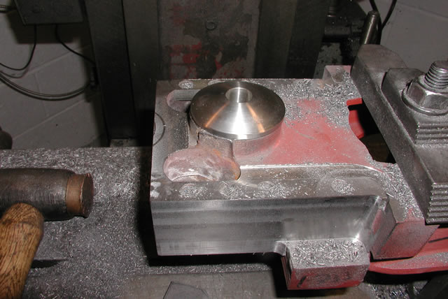
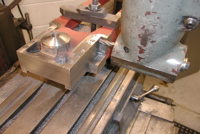
Jim's Fulcrum sitting snug in a 25NC
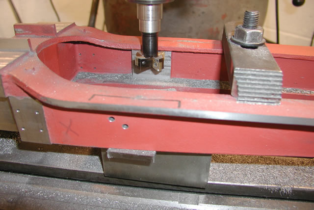
Next job was to machine a chamfer on the front face. The purpose of this was to provide clearance to the radius left by The cutter which you can see in the first picture of the frame side shown above.
Next thing to tackle was the two faces around the front boiler support. The bit of machining highlighted the versatility of the Bridgeport mill which was invaluable in producing the finished casting.
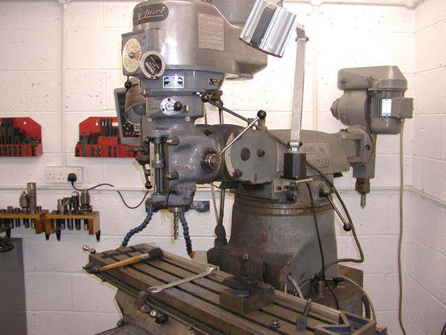
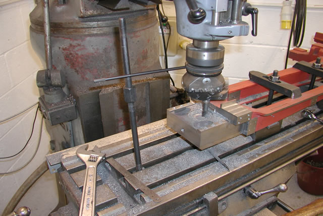
The mill ready for its work out, As you can see the head is virtually moveable in any direction you can think of
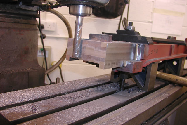
Once the roughing cuts had been done with my trusty 16mm cobalt cutter it was time for the right angle attachment to be fitted to the Bridgeport head
Milling the boiler support faces
Using the right angle attachment with a smaller diameter cutter in it also had the benefit of reducing the radius left in the corner. With this cutter I was also able to machine the large radius left by the 16mil cutter in the corners. The last job on the tongue in this position was to drill and tap a M12 hole in the front face. What's that for ? more on that later.
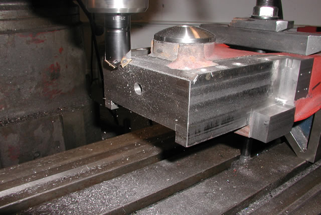
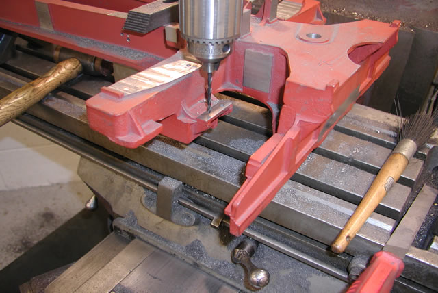
The Bridgeport head is supported on what they call a ram. This arm or ram is moveable and if the screen your looking at was supported by it the ram could move it either closer or further away from you. This proved very hand as it enabled me to machine the back side of the casting without the need to reposition the casting on the mill bed. This meant I was able to machine the bases for the platform supports and some of the holes that are used by the ashpan on both sides without moving the casting.
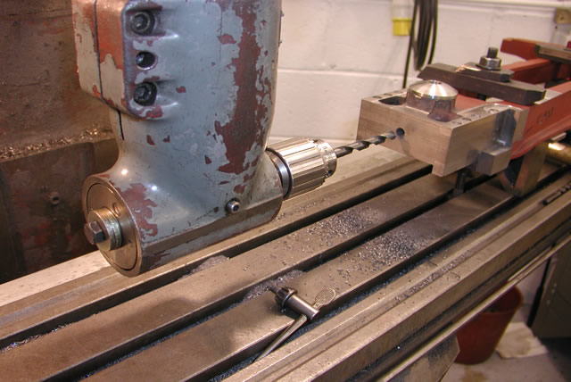
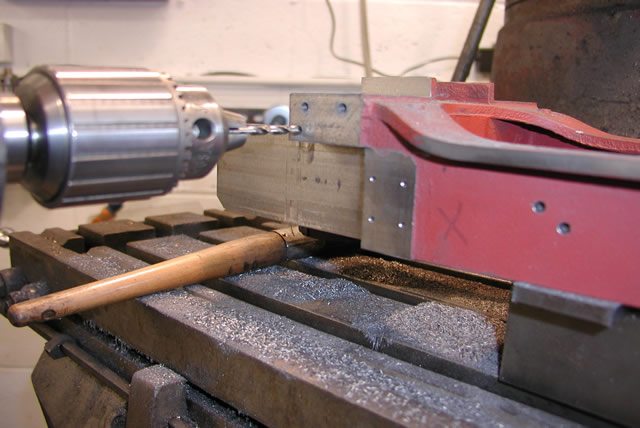
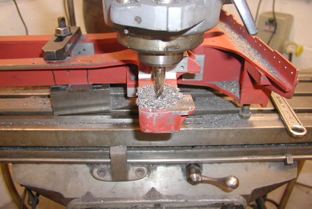
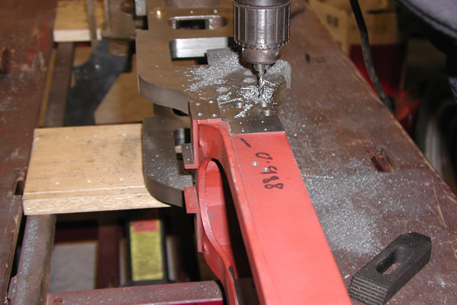
Drilling the ashpan support holes
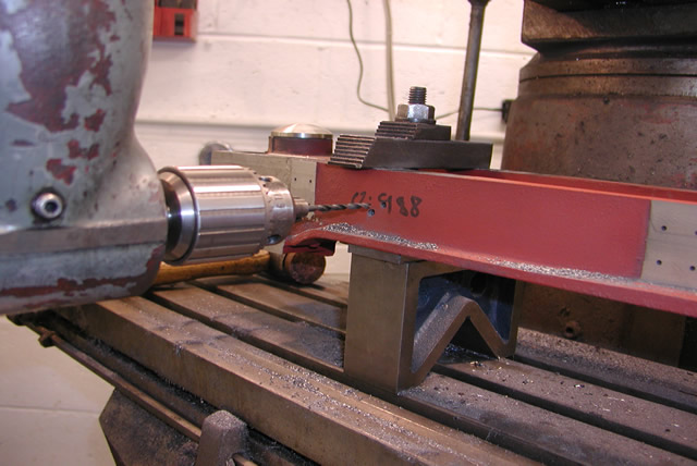
Holes on the back side with the ram moved all the way back to get the right angle head in.
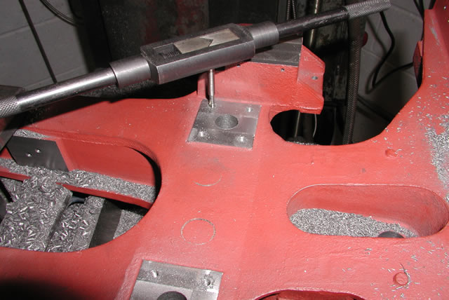
For this casting the right angle head is going to turn up throughout this page. It was worth every penny, all hail eBay So the next thing to do was the thing I hate most and that was move the casting, but it had to be done. Once moved and set up again using the dial gauge. I set it so that I could just pick up the center of the fulcrum and from this set of the holes where the rear rocker plates bolt on. The rear of the casting has a variety of bosses and protrusions on it. Some of which I am still not sure what purpose they serve but we will worry about that when I get to drawing the mating parts later
 .
.
Rocker base being machined single hole to match rocker when fitted.
Next job was to machine the faces of the various blocks and plates ready to drill any mounting holes needed in them..
In the two images above you can see a rectangular face that is machined for a cab platform support. I spent hours fiddling on trying to get the right angle attachment in here with a chuck on it. Then without a chuck just a collet. Then with the drill in a piece of round bar to act as an extension. but eventually I had to give up. At some stage I will need to drill the holes probably using a pistol drill but I will wait until I get the support made and match drill through it.
Well that was it the first two set ups done and time to turn the casting over. to make a start on the other side.
No cutters in the mill ready to slacken off the clamps.
First job after setting up the cradle back right side up was to finnish machining the tongue to size. If your wondering what all the bolt holes are well hands up. Always check your drawings to ensure you don't have a different dimension for the slot and the tongue.
Machining the top face to two inches thick
Once the top had been established it was easy then to set off the height of the front boiler supports. Which were then machined to the correct height
Front boiler supports
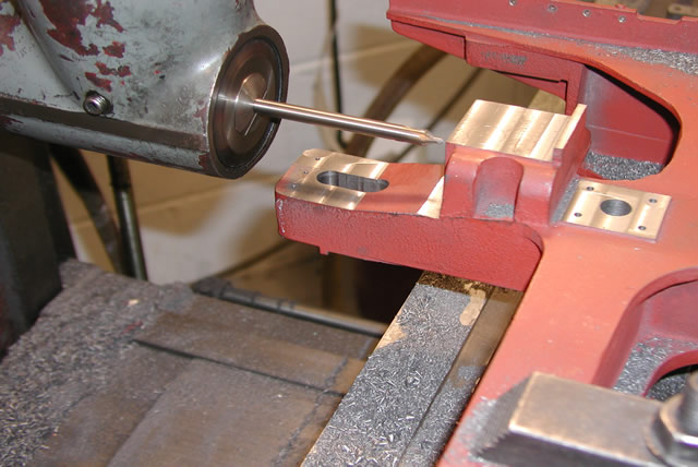
Once the boiler supports were done it was time to do some machining on the inside where some of the brackets for the ash pan fitted. The rear two were fairly straightforward just setting the distance off the wall to get the required depth of face.
Cutting the face on the rear ashpan boss
The rear boss was easy as it was not covered by the web above it. On the other hand the front one was covered and I made use of an old key cutter to get under the lip
Press ganging the key cutter on the front boss
Now it was back to a bit of right angle milling to get the bolt holes in the front boiler supports. I did this by just touching the top with the digital edge finder to establish the top edge. Doing the same on the side and the using the digital read out to work away from the center to get the correct positions for the holes. A lot more complicated to write than do by the way.
Front boiler support holes
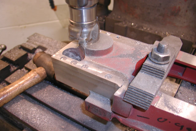
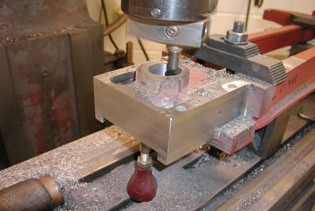
I repeated the same procedure for the right hand side then there was just one more job to do at this setting and this was to mill the fulcrum boss rebate on the top side. The is just a deep hole where the pivot bolt sits. It was slightly more complicated as I was going to use surfacing head to machine the hole. Another eBay purchase this would be the first time I had used it in anger and I was not that confident of success. Things were not helped by the instruction book that used a dialect of English called Czechlish.
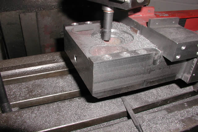
Using the Narex boring head to face out the hole
So perhaps a few words of explanation on what is happening. using a conventional boring head you set the diameter and the head rotates at that preset size which you then move vertically to create the bore. However with this head you can also set the depth and the head itself when rotating will slide outwards creating an ever larger diameter of hole at the depth you have set. To do this the head is locked using the plain horizontal rod checked against the vertical table bolts. There are a couple of little stops on the sliding portion of the head and when the head slides to this predetermined size it disengages with a disconcerting clunk. Well it all went surprisingly well, so that effectively completed the front. It was now time to concentrate on the rear boiler supports and the back of the casting
To do this the cradle had to be moved again this time far enough to allow the right angle attachment to get behind the cradle to machine rear face where the rubbing block fits against the tender.
Setting up the casting to machine the rear face
You would have thought that setting the casting up on this face would have been the easiest setting to accomplish but as it turned out I had a fair bit of trouble getting it somewhere near. The main problem was the rear face was wider than the travel on the bridgeport table so it meant I would have to machine it at the settings moving the ram in and out to get everything done. I first set the face up using a straight edge clamped onto the face only lightly I hasten to add. Unfortunately this was OK but their were problems round the corner which we will get to later.
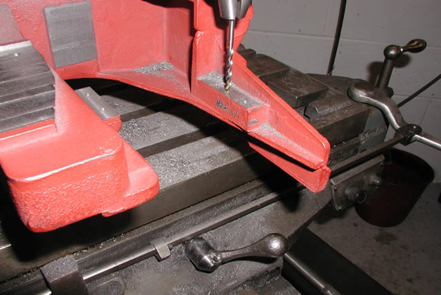
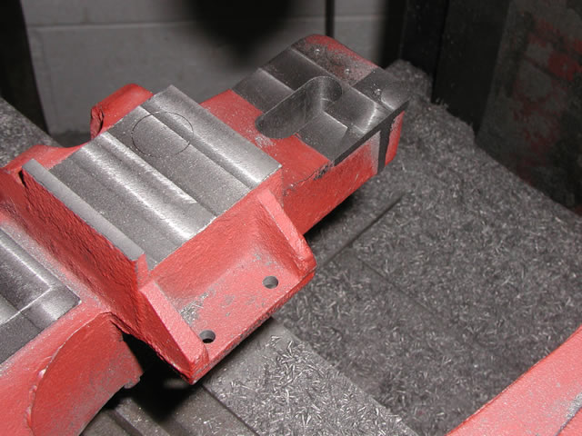
Along the top edge of the back face is a little rebate this is where the rear cab support plate sits This proved quite testing to get set up correctly due to the need to move the head out to accommodate the extra width.
Although its not clear from this picture this was the area of most concern on the whole casting. Because the wing behind the cutter is overall 16" wide and only 0.2" thick at the extremities, on casting some warping had taken place. If it had been steel I would have had no worries about giving it a bit of punishment with a 2lb-er but cast iron is a different matter so I left well alone. However across it length this did mean that the ledge got thinner where the warp was and this resulted in some 0.02" of taper.
Next on the agenda was drilling the back face, first job was the holes for the rear cab support plate. This had previously been laser cut but I had only put a few holes in it and once mounted intended drilling through the plate to ensure no slip ups.
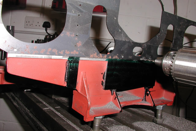
Drilling the rear cab support plate
The plate is held on by 18 bolts so the boys at North British were making sure it would not fall off. Next I temporarily mounted the cab support angles so I could match drill them as well
Last job on the back face was to drill and tap the four mounting holes for the rubbing block
Tapping the rubbing plate mounting holes.
Next job was to face off the two bosses between the rear boiler supports. a pretty straight forward job then onto the rear boiler supports Once faced there were four tapped stud holes and a central 1/2" hole to drill
Then it was onto the rear boiler supports, which I though was just a carbon copy of the front ones. Sadly what I forgot is that they sat much wider than the front pair and because of this I could not machine them without moving the head and I could not get in to drill any of the holes using a chuck and had to buy a couple of long reach drills to do the job.
Machining the front boiler support face
Using the vernier height gauge to check the height of the rear support relative to the front one
Using a long reach center drill to spot the four bolt holes
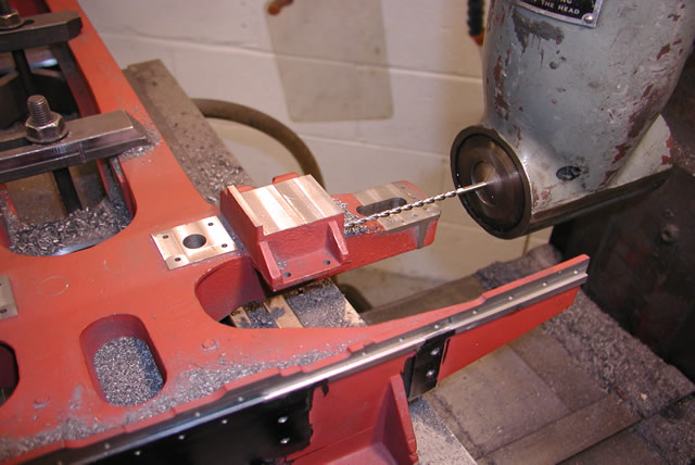
Long reach 4.2mm drill for bolt holes
Prior to drilling the holes i had to machine an undercut on the front face so the plate that fits on it can hook under the face against this undercut.
 ##
##
Using a a 5/16 mill to form the undercut
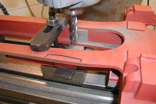
By now I was on the home straight and had only a couple of jobs left first was to machine the mounting plate on the left hand wing and drill a couple of holes in it. The plate can be seen in the above shot. The holes don't look like they are in the correct position maybe its just that the front hole is not on the center of the radius of the plate but they do look a bit odd
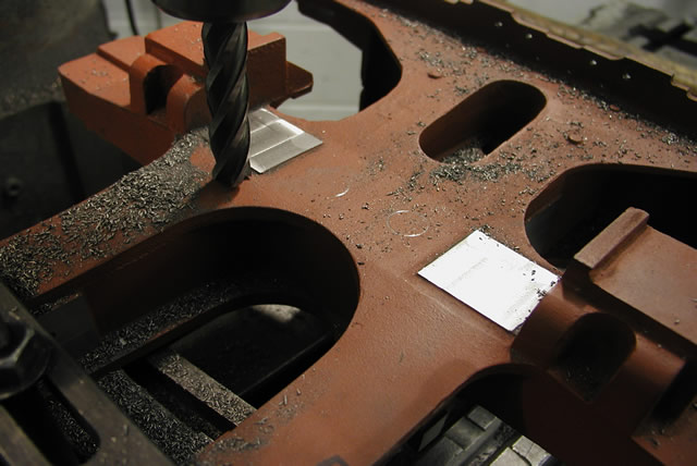
Next was to mill out a couple of core holes that were on the full size pattern but were a bit overcomplicated to produce in mine. I also had to drill three little holes on the right hand wing for a piece of angle which carries the speedometer pick up
The three small holes for the speedometer pick up bracket
Now another mistake to share with you, in autoCad is a command called mirror this means that you can create a mirror image of anything you have drawn thus saving you a lot of time drawing things twice. However you should remember to delete any objects not needed in the mirrored part. Well the little mounting plate on the left hand wing is not on the right hand wing. I must have mirrored the whole of the wing and forgot to delete the little mounting plate, So if you look closely you can see where I had to machine it off.
And that was all she wrote the basic machining was finished and all that was left was to give it a good clean off prior to the big show and getting it to fit the frames.
All machining finished and ready to clean down.
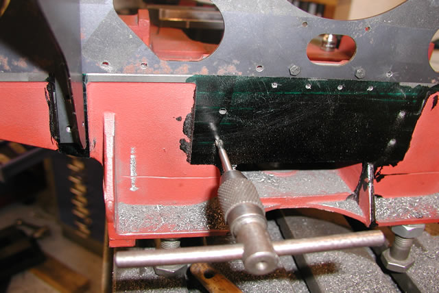
So remember the M12 hole well I knew I would need something to pull the casting into place hence the hole which allowed me to pull off the rear axle pedestal faces.
Once I had the cradle pulled into the frame held by the M12 puller I turned the whole frame on its side and transfer punched through onto the casting prior to drilling the M6 holes using an old electric drill I have.
I then fitted all the bolts required and it was job done. I turned the frame back the right way up and admired my work. Which went far better than expected when I came to fit the casting to the frame. It also looks just as I expected and once I get the holes filled up will take on the appearance of the cast bed I was after.