
Tender Tank
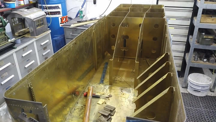
The tender tank came as a CNC punched and folded kit. One slight problem was the kit had been produced before Jim had made his design for the tender tank. I understand a number of these kits were produced in America for early builders of the locomotive. However working to Jims drawings presented some difficulties as the kit and his drawings don't necessarily agree in all areas.
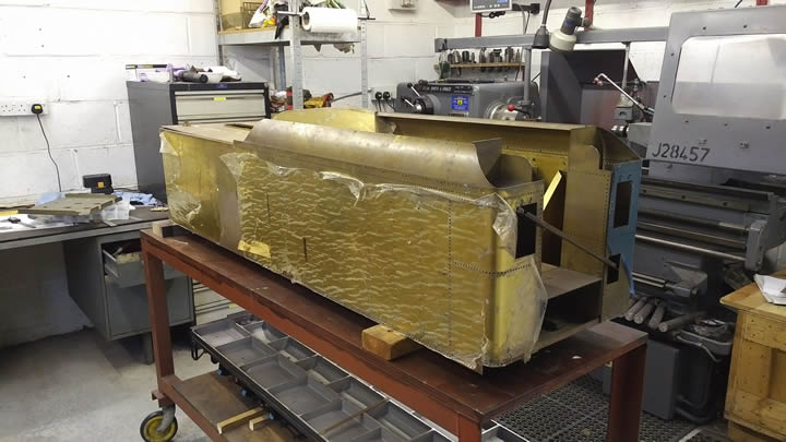
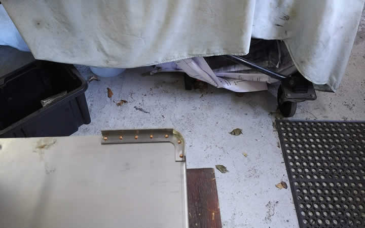
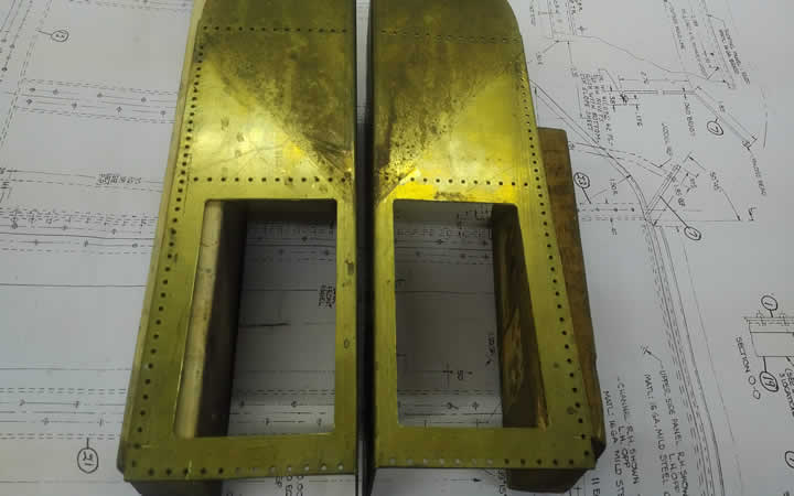
Tender tank prior to dismantling
The kit was designed to fully replicate the coal space and the stoker tunnel neither of which feature in Jim's design so for this model would have to be thrown away. So the first job was to dismantle the kit which was temporarily held together with nuts and bolts
Coal side sheets and stoker tunnel
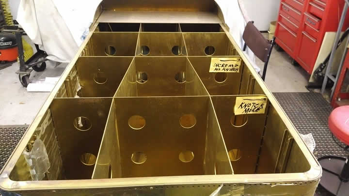
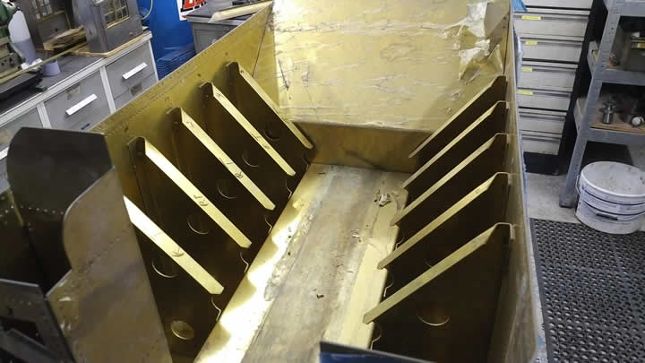
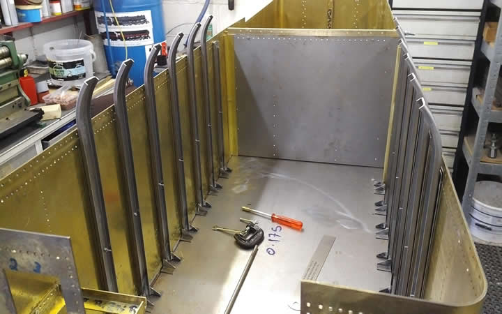
Water tank with folded baffles
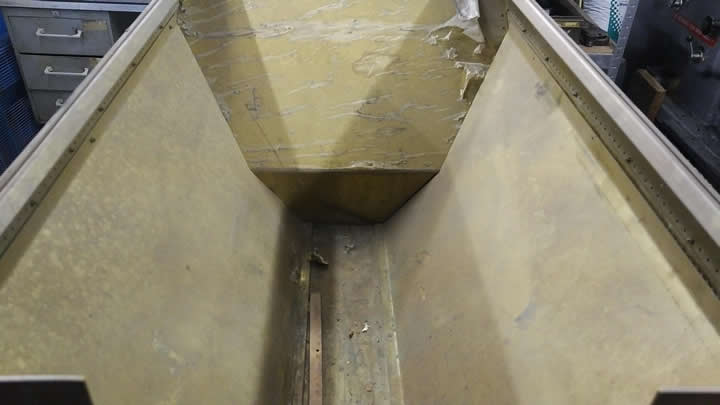
Coal sheets removed
Most internal sheets removed.
Once the tank had been disassembled i discovered that the tank floor was not close to Jim's design and could not be modified to suite. So the first job was to commission a new tender tank floor. This proved to be very problematic and i approached three different dealers all of whom let me down before i finally got a bed folded. However my problems were still not at end as the floor had been folded incorrectly when my measurements were transferred to the vendors folding software he put the wrong width dimension in. So there was another six week's delay waiting for a replacement
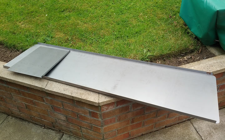
New tender tank floor and internal baffle, CNC folded
First job on the floor was to fit three internal channels that the sides bolt too at the front and rear of the tank. On Jim's drawings there were folded round formers. As i have a CNC mill i machined them from the solid and then they were riveted to the bed with 1/16 and 3/32 rivets
Internal corner angles being machined on the Tormach
Completed internal corner.
Once the corer brackets had been machined it was time to rivet them to the tender floor The rear brackets were secured with 1/16 rivets and the front pair were secured with 3/32.
Rear corner brackets fitted
Front corner brackets fitted
The floor was heavily counter sunk on the bottom face so the rivet heads could be sanded flush with the rest of the out floor.
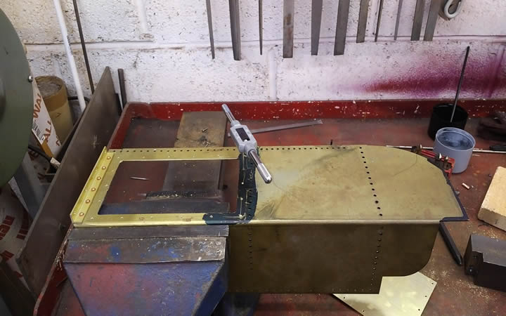
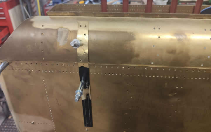
I then test fitted the rear two tank sides, to hold them in place prior to riveting a made up two clamps that utilised the existing holes in the sides used for the channels. The clamps were secured so that the sides could still slip to make sure I did not induce a kink into the sides once I stated fitting them round the curved corners. I temporarily secured the back seam using a channel piece and some celco's and then drilled through the corners working round the radius to ensure it fitted round and secured the sides with temporary bolts..
Sliding clamps added to hold the sheet to the angle
Celco's through the sheets to the channel
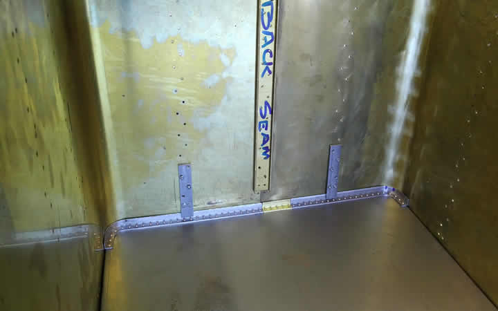
Side sheets secured ready to drill
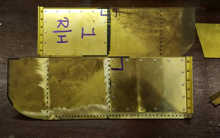
Next part of the process was to fit the front two sheets and match drill them to the floor fitting temporary celco's to secure the sides. The corners were once again wrapped round the curve to ensure no kinks were induced. Working round the corners they were drilled and temporary bolts fitted prior to riveting.
Match drilling the laser cut holes in the sides through to the floor. Then securing with cleco's
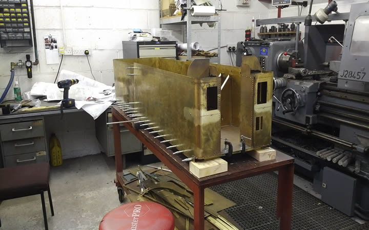
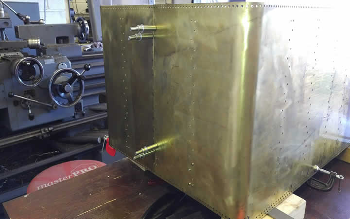
All four sides secured to the floor.
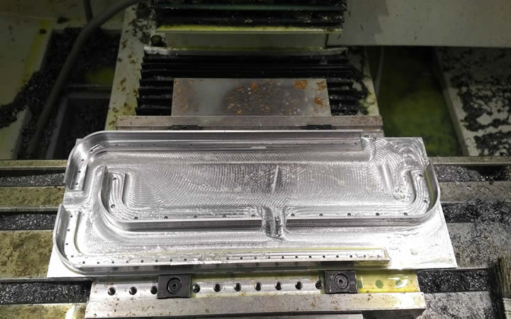
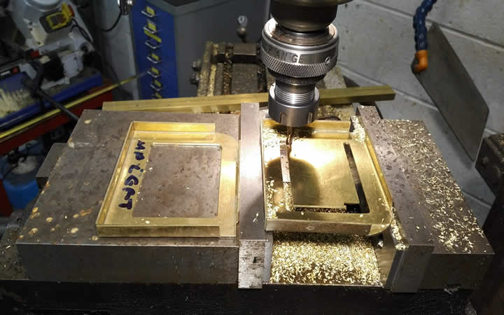
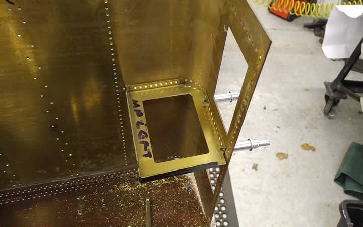
The next sub assembly to look at was the front two corner towers. They were both CNC folded but need a bit of modification to use on the Krider design. Both towers needed access hatchways cutting in them and the internal baffle plates also need modifying. First job was to machine the access hatch and fit the covers
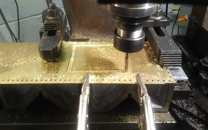
Machining the access hatch opening
Both towers machined
Tapping the access hatch cover holes M2.5mm I also fitted the tower to floor angles at the same time
Both covers and sides to floor angles fitted and riveted up.
The two towers both have an internal baffle fitted , this also needed to be opened up to allow if required water valve extensions to pass through to the top baffle. I am not sure as yet I am going to follow that route but they had to be opened up prior to fitting..
Machining out the baffle plate access
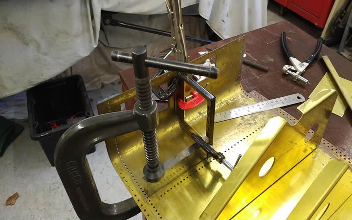
Setting up the baffle for match drilling
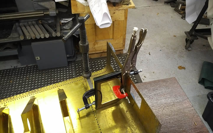
You can never have enough clamps
Baffle in place.
Once the baffle was in place I riveted up the out two faces due to the tower covering access to the inside faces they will be secured with dome head screws to match the rivets and dummy rivets elsewhere. As it turned out I had to remove all the rivets to adjust the fit of the covers above this middle baffle and get it sitting square with the rest of the side sheets. So in future pictures you will see this are is pretty clean as I gave it a rub up with some emery cloth once the rivets had been removed.
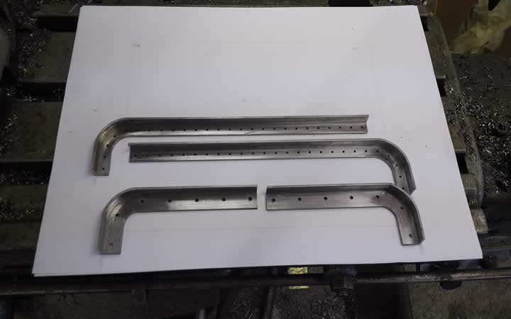
With the sides and back now fitted to the floor the basic shape of the tender was done. It needed stiffening up though as it was like wet spaghetti. To do this the first job I tackled was fitting the side channels to what would have been the coal space on the full size unit.
To produce the channels I had some plate CNC folded to the correct profile. The channels then needed to have a slow bend on one end as they were fitted under the coal boards. To do this I had a mild steel former laser cut then thinned down to suite the channel.
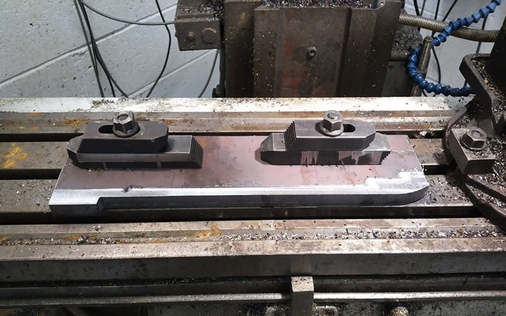
Bend jig on mill for thinning
Once the jig was ready the channels were clamped to it and the ends were formed round with the help of a bit of brute force.
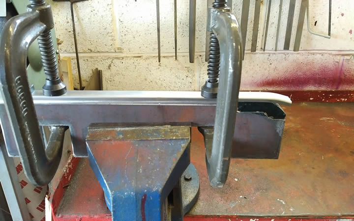
Ready to bend
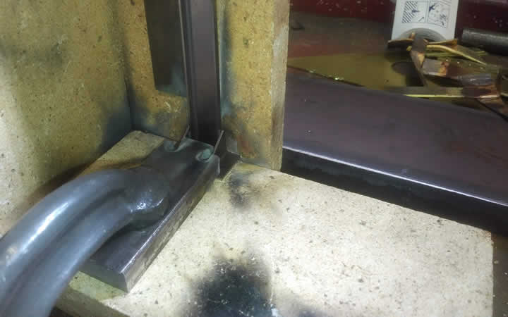
Once bent up they needed to be fitted with a small foot bracket that once again was CNC folded. Then i made up a brazing fixture to braze the feet on.
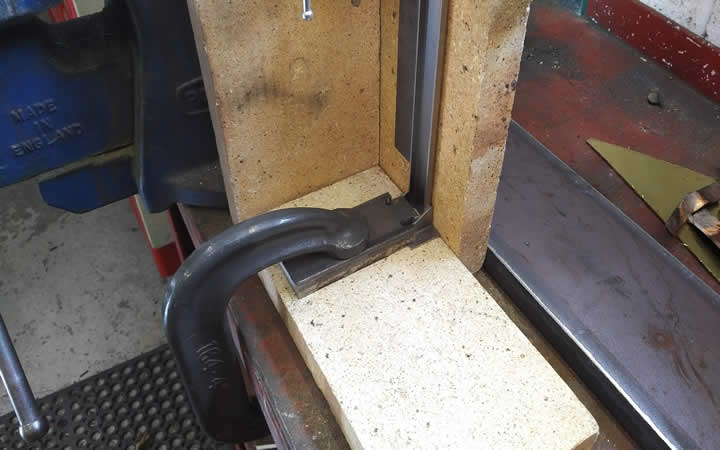
Brazing fixture to fit feet.
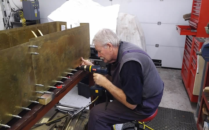
The Legs were then put back on the mill to have two holes drilled in the bottom which matched the tender sides.
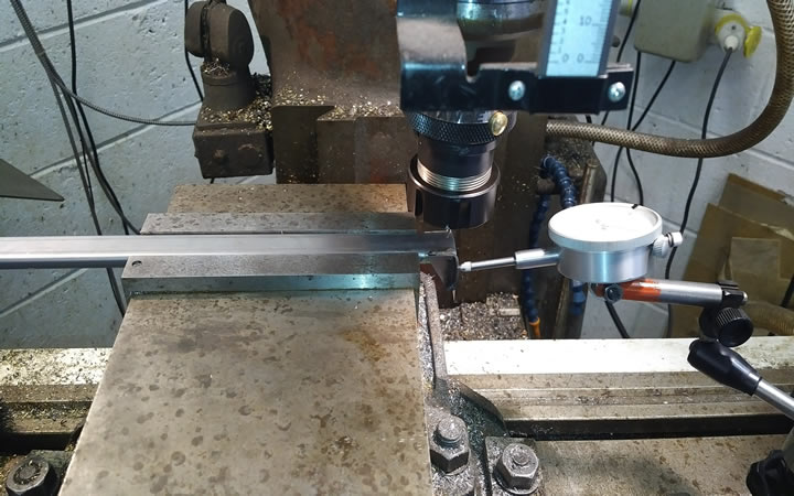
Drilling the bottom two 3/32 rivet holes.
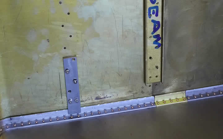
These two holes were the datum holes for each channel. The foot hole was transfer punched through onto the bed and drilled and taped M2.5 . Then each channel was g clamped to the side sheet and check for square then the rest of the 3/32 rivet holes were match drilled through..
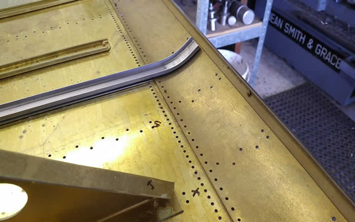
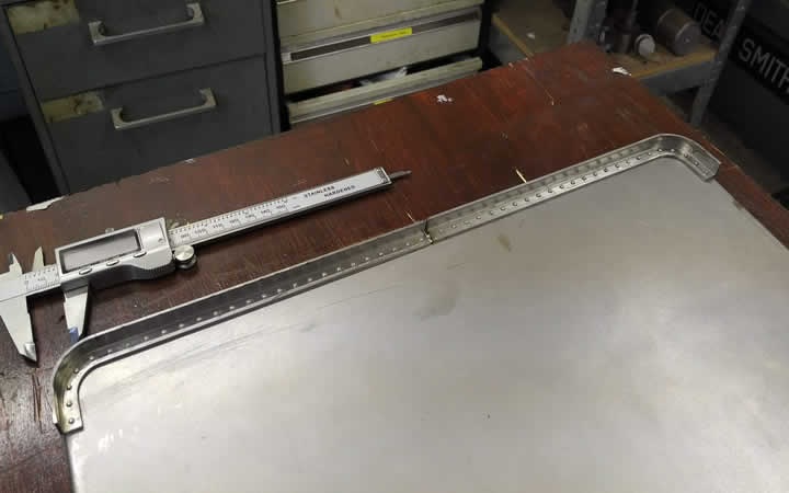
As can be seen from the above snap to accommodate the coal board thickness each channel had a 1/16" spacer fitted behind it which also had to be matched drilled at the same time. One more anomaly seen here is the coal boards punched holes don't match the side sheet spacing so all had to be filled in and re drilled.
All side channels in place with temporary screws fitted
Template used to transfer the correct hole pattern to the coal boards.